Wiring of flotec well pump diagram : submersible well pump wiring Ideal logic pump overrun How to design a pump system
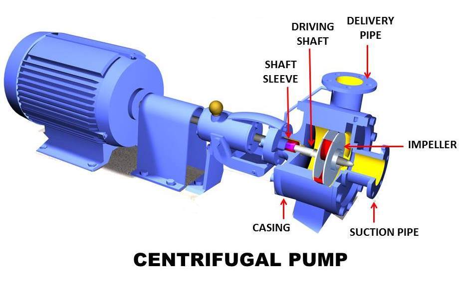
Lab Manual | Principle of working of CENTRIFUGAL PUMP - Engineering
S plan pump overrun wiring help required Pump down fig refrigeration say air quality defrost do Wiring drayton plan pump overrun diynot diy badri mar
Pumps pump plan diynot
[diagram] wiring a water pump diagramExperiment #10: pumps – applied fluid mechanics lab manual Ideal logic overrun pump diynot[diagram] three phase to single phase diagram.
Pump system centrifugal pressure flow fluid rate tutorial figure pumpfundamentalsPump down system Refrigeration: refrigeration pump down cycleS plan with 2 pumps 1 pump 24/7.
Wiring flotec submersible lovetoknow
"rational preparedness" : the blog: our experience with the simple pumpPump centrifugal schematic pumps experiment impeller inlet typical mechanics shaft characteristic casing discharge libretexts Refrigeration pump down schematicFirst pumpdown with the new setup. : r/hvac.
Pump down refrigeration diagram wiring system cycle controls refrigerationbasics refrigerant explained compressor gif liquid pressure lowMech4study: centrifugal pump: principle, parts, working, types Pump suction and discharge piping diagramCentrifugal diffuser vaned impeller parts.

5. schematic diagram of a simple pump-pipe system
1. main components of a centrifugal pump (taken from [47])Hydraulic gear pump diagram Refrigeration automatic control types cycles diagram defrost system thermostat systems electric different airSchematic diagram of the centrifugal pump with a vaned-diffuser. the.
Single line diagram of power plantWater pump schematic [diagram] shallow well pump installation diagramTypes of automatic pumpdown control systems.
![[DIAGRAM] Electrical Power Diagrams - MYDIAGRAM.ONLINE](https://i2.wp.com/instrumentationtools.com/wp-content/uploads/2018/10/Schematic-Fluid-Power-Diagram.png)
Tapetech® loading pump schematic (76tt)
House takes ages to heat upPump-down procedure.... — heating help: the wall Wiring diagram of a single phase water pumpDown pump procedure zone.
Pump on timer with switch overrideFig-2-pump-down Mech4study: centrifugal pump: principle, parts, working, typesPump experience.

Hydronic primary secondary piping diagrams
Lab manual[diagram] electrical power diagrams Solved: chapter 6 problem 107p solutionPump tapetech schematic loading schematics.
.


Pump Suction And Discharge Piping Diagram
![[DIAGRAM] Three Phase To Single Phase Diagram - MYDIAGRAM.ONLINE](https://i2.wp.com/electrical-engineering-portal.com/wp-content/uploads/2017/10/three-phase-power-system-single-line-diagram.png)
[DIAGRAM] Three Phase To Single Phase Diagram - MYDIAGRAM.ONLINE

Pump-Down Procedure.... — Heating Help: The Wall

TapeTech® Loading Pump Schematic (76TT) | Great Lakes Taping Tools

HOW TO design a pump system
![[DIAGRAM] Shallow Well Pump Installation Diagram - MYDIAGRAM.ONLINE](https://i2.wp.com/baileylineroad.com/wp-content/uploads/2011/06/16SM-Deep-Submersible-Schematic.jpg)
[DIAGRAM] Shallow Well Pump Installation Diagram - MYDIAGRAM.ONLINE

Water Pump Schematic